Wired
The Wired view presents the scaffolds associated with configuring the wired distribution layer of your network, and monitoring/configuring the switch ports throughout your infrastructure.
Switches
An entry in the switches scaffold defines a piece of switching equipment with which the rXg will communicate for the purpose of effecting dynamic VLAN changes when necessary due to a policy shift for a device on the network.
When a device's VLAN assignment has changed due to a policy shift, the rXg will connect to the switch associated with the device's RADIUS realm via the protocol specified in the configuration, and force a disconnect/reconnect, which will reinitiate the RADIUS authentication process, thereby resulting in the new VLAN assignment being applied to the client device.
The name field is an arbitrary string descriptor used only for administrative identification. Choose a name that reflects the purpose of the record. This field has no bearing on the configuration or settings determined by this scaffold.
The device section specifies information of equipment being configured. Fields with bold text are required. Choose the appropriate option from the supported device types drop-down menu.
Enabling the Monitoring checkbox results in the rXg attempting to import and synchronize Switch Ports from the device, as well as perform ping monitoring of the switch itself, and collect CPU and Memory statistics, where possible.
The SNMP community field specifies the SNMP community string that will be used when attempting to gather CPU and/or Memory information, as well as to collect Switch Port utilization/error/discard data for graphing.
The Switch Fabric field assigns a switch fabric profile to this switch. The Loopback IP , System name , and SPB-m nickname fields must be provided when assigning a switch fabric profile. After supplying the necessary information, the Config sync status link becomes available in the scaffold.
For switches that support configuration management, the Config sync status column contains a link that allows the operator to access bootstrap instructions and enable synchronization.
When bootstrapping a new switch, the operator may retrieve bootstrap commands that will bring a factory default switch or wireless controller into the necessary state to participate in the fabric network, which may be copy/pasted into a console session on the device.
After initial bootstrapping and network connectivity is established, the operator may download a running configuration backup or compare the current running configuration to the expected configuration, based on the associated configuration elements. If changes are needed, they may be pushed to the switch. After successfully synchronizing manually the first time, future configuration changes will be pushed to the device whenever relevant configuration changes are made in the database.
The note field is a place for the administrator to enter a comment. This field is purely informational and has no bearing on the configuration settings.
Automatic Onboarding
Supported switch types (such as Cisco Catalyst IOS-XE and EdgeCore) can be automatically onboarded from a factory-default state. This process eliminates the need to manually configure the switch via console before it can be managed by the rXg.
Prerequisites
Before initiating automatic onboarding, ensure the following:
- The switch must be connected to the network and able to obtain a DHCP address from the rXg.
- Create a switch record in the Switches scaffold with the desired target IP address (the management IP the switch will be assigned after onboarding).
- Enter the switch's MAC address in the device record. This allows the rXg to locate the switch on its temporary DHCP address.
- Configure the Management VLAN if different from VLAN 1.
- Provide valid SSH credentials (username and password) that match the switch's factory default or pre-configured credentials.
Onboarding Process
- Click the Auto Bootstrap action link in the switch record.
- The rXg looks up the switch's current DHCP IP address using the configured MAC address from the DHCP leases table.
- An SSH connection is established to the switch using the temporary DHCP IP.
- The system detects whether the switch is in factory-default state by checking for the absence of rXg-specific configuration elements (varies by switch model).
- If factory-default state is detected, bootstrap configuration is automatically applied, including:
- Management VLAN creation (if not VLAN 1)
- Static IP address assignment on the management VLAN interface
- Default gateway configuration
- SNMP community string
- AAA and RADIUS configuration for 802.1X
- Uplink port trunk configuration to carry the management VLAN (with native VLAN 1)
- NTP server configuration
- The switch saves its configuration and reconnects on the new management IP address.
After automatic onboarding completes, the switch will appear as online at its configured management IP address and will be ready for configuration synchronization.
Uplink Port Configuration
During automatic onboarding, the uplink port (default: GigabitEthernet1/0/1) is configured as a trunk port to carry both the native VLAN 1 (untagged) and the management VLAN (tagged). This allows the switch to maintain connectivity during the transition from DHCP to static IP addressing.
The trunk configuration is applied in the following order to minimize connectivity disruption:
- Trunk properties are configured first (native VLAN 1, allowed VLANs) while the port remains in access mode
- Configuration is saved to startup-config
- The port mode is changed to trunk, which causes a brief (~30 second) port flap
- The switch reconnects on its new management IP
Manual Onboarding
For switches that do not support automatic onboarding, or in situations where manual configuration is preferred, the operator may retrieve bootstrap commands and apply them manually.
- Create a switch record with the desired management IP address and credentials.
- Click the Config sync status link to access bootstrap instructions.
- Retrieve the bootstrap commands that will bring a factory-default switch into the necessary state.
- Connect to the switch via console cable or existing network access.
- Copy and paste the bootstrap commands into the switch's CLI session.
- After the configuration is applied, the switch will be reachable at its new management IP address.
Refer to the Switch Model-specific Configuration Details section below for detailed manual configuration steps for each supported switch type.
Switch Fabric
An entry in the Switch Fabric scaffold defines the fabric area of a 802.1aq Shortest Path Bridging-MAC (SPB-m) deployment. All participating fabric switches share the common configuration found here. In addition, each participating fabric switch should have an Infrastructure Device defined with the necessary SPB-m configuration specific to that device.
The name field is an arbitrary string descriptor used only for administrative identification. Choose a name that reflects the purpose of the record. This field has no bearing on the configuration or settings determined by this scaffold.
The Management I-SID field specifies the I-SID that will be associated with the Management VLAN for management traffic. The Management VLAN is configured per device, under the Switches scaffold.
The Manual area field specifies the IS-IS area that will be used within this fabric in the format: xx.xxxx (ex: 10.0001)
The Primary B-VLAN and Secondary B-VLAN fields indicate the VLANs which will be used for passing encapsulated traffic between participating fabric switches on switch ports designated as NNI ports. These VLANs should be unused elsewhere in your infrastructure.
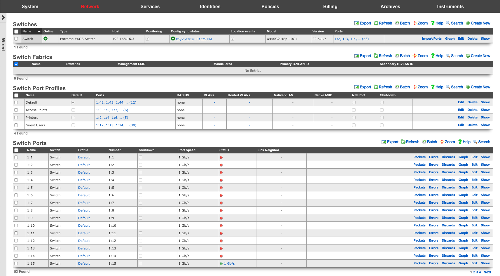
Switch Ports
Entries in the Switch Ports scaffold are created automatically by enabling the Monitoring checkbox on a supported switch's Infrastructure Device. Ports are imported and speed, packet, error and discard rates are gathered via SNMP and made graphable for each switch port.
The name field represents the port's identification in the switch, and should not be changed.
The NNI Port designates this port as a Network-to-Network Interface. This option must be enabled for any port where two fabric-enabled switches interconnect.
The speed in bps field represents the port's maximum physical speed in bits per second.
Link Aggregation Groups (LAG)
Link Aggregation Groups (LAG), also known as port-channels or EtherChannels, allow multiple physical switch ports to be bundled together into a single logical interface. This provides increased bandwidth through load distribution and redundancy through automatic failover if a member link fails.
Supported Switch Types
LAG configuration management is currently supported on:
| Switch Type | LAG Support |
|---|---|
| Ruckus ICX | Fully supported |
| Cisco IOS | Not supported at this time |
| Cisco IOS-XE | Not supported at this time |
| Dell | Not supported at this time |
| EdgeCore | Not supported at this time |
For switches that do not support LAG management through the rXg, LAG interfaces must be configured manually via the switch CLI.
LAG Types
The rXg supports two types of LAG configurations:
| LAG Type | Description |
|---|---|
| Static | Member ports are manually assigned and do not negotiate with the remote device. Use when connecting to devices that do not support LACP. |
| Dynamic | Uses Link Aggregation Control Protocol (LACP / IEEE 802.1AX) to negotiate the aggregation with the remote device. Provides automatic detection of misconfigured or failed links. |
How LAG Ports Appear
When monitoring is enabled on a supported switch, LAG interfaces are automatically imported alongside regular switch ports. The port naming convention varies by switch vendor (e.g., on Ruckus ICX switches, LAG ports use the lg prefix such as lg1, lg2, lg3).
In the Switch Ports scaffold, LAG interfaces display:
- Name: A descriptive name for the LAG (e.g., "Uplink-LAG", "Server-Bond")
- Port: The LAG identifier (e.g.,
lg1on Ruckus ICX) - Port Type: Either "Static" or "Dynamic"
- Sub Interfaces: The member ports that belong to this LAG
- Speed: The aggregate bandwidth of all active member ports
Creating a LAG Interface
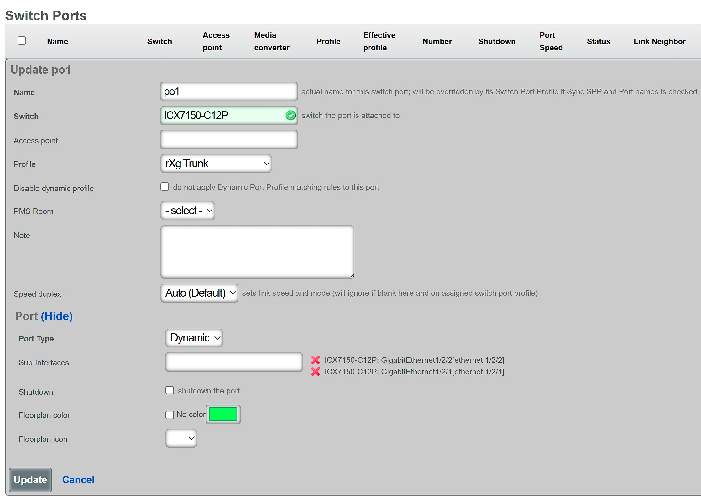
To create a new LAG interface on a supported switch (using a Ruckus ICX switch as an example):
- Navigate to Network :: Wired :: Switch Ports
- Click Create New to add a new switch port record
- Select the target Infrastructure Device (must be a supported switch)
- In the Port section:
- Leave the Port field empty (it will be auto-assigned, e.g.,
lg1,lg2on Ruckus ICX) - Set Port Type to either Static or Dynamic
- Select the Sub Interfaces (member ports) to include in the LAG
- Leave the Port field empty (it will be auto-assigned, e.g.,
- Assign a Switch Port Profile to define VLANs and other port settings
- Provide a descriptive Name for the LAG
- Click Create
The following example shows LAG creation on a Ruckus ICX switch:
The rXg will automatically generate and push the appropriate LAG configuration commands to the switch during the next config sync.
Modifying a LAG Interface
To modify an existing LAG:
- Navigate to Network :: Wired :: Switch Ports
- Locate the LAG interface (e.g., ports starting with
lgon Ruckus ICX) - Click Edit on the LAG record
- Modify the desired settings:
- Name: Change the descriptive name
- Sub Interfaces: Add or remove member ports
- Switch Port Profile: Change VLAN assignments or other settings
- Shutdown: Enable to administratively disable the LAG
- Click Update
Important Notes: - The Port Type (Static/Dynamic) cannot be changed after creation. To change the LAG type, delete the LAG and recreate it with the desired type. - A LAG must have at least 1 member port and no more than 8 member ports. - LAG interfaces cannot have RADIUS authentication enabled (802.1X or MAB). The switch port profile assigned to a LAG must have RADIUS authentication set to "None".
Deleting a LAG Interface
To delete a LAG:
- Navigate to Network :: Wired :: Switch Ports
- Locate the LAG interface
- Click Delete on the LAG record
- Confirm the deletion
When a LAG is deleted: - All member ports are released and become individual ports again - Member ports are automatically disabled to prevent network loops - The ports can then be reassigned to profiles or new LAGs as needed
LAG Configuration on the Switch
The rXg automatically generates and pushes vendor-specific LAG configuration commands to the switch. The following example shows the commands generated for a Ruckus ICX switch:
! Create a dynamic LAG with LACP
lag "Uplink-LAG" dynamic id 1
  ports ethernet 1/1/1 ethernet 1/1/2
exit

! Create a static LAG without LACP
lag "Server-Bond" static id 2
  ports ethernet 1/1/5 ethernet 1/1/6
exit
VLANs configured on the LAG's switch port profile are applied to the LAG interface, not to individual member ports.
Best Practices
Use Dynamic LAGs when possible: LACP provides better failure detection and prevents misconfigurations from causing loops.
Match configuration on both ends: Ensure the remote device (switch, server, etc.) has matching LAG configuration:
- Same number of member ports
- Same LAG type (static requires static, dynamic requires LACP-enabled)
- Same VLAN configuration
Use consistent port speeds: All member ports in a LAG should have the same speed and duplex settings for optimal load distribution.
Plan LAG IDs: Different switch vendors have varying limits on LAG IDs (e.g., Ruckus ICX supports IDs from 1 to 256). The rXg auto-assigns IDs, but be aware of vendor-specific limits in large deployments.
Monitor LAG health: Check the Link Speed field to verify all member links are active. The aggregate speed should equal the sum of all member port speeds.
Troubleshooting LAG Issues
| Symptom | Possible Cause | Resolution |
|---|---|---|
| LAG shows lower speed than expected | One or more member links are down | Check physical connections and port status on both ends |
| Dynamic LAG not forming | LACP not enabled on remote device | Enable LACP on the remote switch or use Static LAG type |
| Config sync fails for LAG | LAG name contains invalid characters | Use only ASCII characters (spaces are allowed) in LAG names |
| Member ports not joining LAG | Ports already in another LAG | Remove ports from existing LAG before adding to new one |
| LAG interface is shutdown | All member ports are disabled | Enable at least one member port |
Switch Port Profiles
Entries in the Switch Port Profiles scaffold define the behavior of downstream wired infrastructure device ports. Switch port profiles enable an operator to manage virtually unlimited switch ports, without configuring them individually.
The name field is an arbitrary string descriptor used only for administrative identification. Choose a name that reflects the purpose of the record. This field has no bearing on the configuration or settings determined by this scaffold.
The Default checkbox, declares the selected switch port profile as the default for any newly imported switches
The Move Ports checkbox, if selected, will move ports associated with a different default profile to a profile upon save. This should be used in conjunction with the Default checkbox.
The Ports field defines individual switch ports to associate with this profile.
The Native VLAN field is used to define the untagged VLAN that ports associated to a profile should use.
The Shutdown checkbox declares ports associated to this profile to be disabled.
The VLANs field defines the VLANs that should be tagged on ports associated with a profile.
The RADIUS drop-down menu can be used to enable 802.1x or MAC Authentication Bypass, on ports associated to a profile.
The native I-SID specifies the network that untagged traffic from this port should be placed into when building a Fabric configuration script.
The NNI Port designates this port as a Network-to-Network Interface. This option must be enabled for any port where two fabric-enabled switches interconnect.
The Manual Tagged VLANs field allows specifying additional VLAN tags directly as a comma and/or dash-separated list of integers, without creating VLAN records. These VLANs are unioned (combined) with any VLANs selected in the VLANs field above. For example, 100,400,1400-1409,2000-2099 would add VLANs 100, 400, 1400 through 1409, and 2000 through 2099 to the port's tagged VLAN list. This is useful when integrating with existing infrastructure where some VLAN management is handled externally.
The Speed/Duplex field controls the port speed and duplex settings. Available options are:
| Setting | Description |
|---|---|
| auto (default) | Automatic speed and duplex negotiation |
| 1000-full | Force 1 Gbps full duplex |
| 10g-full | Force 10 Gbps full duplex |
The Hybrid Port checkbox enables hybrid port mode, allowing the port to function as both an access port (with untagged traffic on the native VLAN) and a trunk port (with tagged traffic on specified VLANs) simultaneously. When enabled, the profile must have either a Native VLAN or tagged VLANs configured. Note that hybrid port mode is not supported on all switch types.
The Inline Power field controls Power over Ethernet (PoE) priority for ports associated with this profile. This determines which ports receive power first when the switch's PoE budget is constrained. Valid values are:
| Value | Description |
|---|---|
| 0 | PoE disabled - no power delivered to this port |
| 1 | Critical priority - highest priority, powered first |
| 2 | High priority - powered after critical ports |
| 3 | Low priority - powered last when budget allows |
Leave this field blank to use the switch's default PoE settings. The actual power class (PoE/PoE+/PoE++) is typically negotiated automatically based on the connected device's requirements.
The Edge Protection checkbox enables STP edge port protection (similar to PortFast) on ports associated with this profile. Edge ports transition immediately to the forwarding state, bypassing the listening and learning states. This should only be enabled on ports connected to end devices, not on ports connected to other switches.
The STP Protect checkbox enables STP BPDU Guard on ports associated with this profile. When enabled, if a BPDU is received on the port, the port will be disabled to prevent potential loops. This is typically used in conjunction with Edge Protection on access ports.
The Trust DSCP checkbox enables DSCP (Differentiated Services Code Point) trust on ports associated with this profile. When enabled, the switch will honor the DSCP markings in incoming packets for Quality of Service (QoS) prioritization. This is useful for VoIP phones and other devices that mark their traffic for priority handling.
The Optical Monitor checkbox enables optical transceiver monitoring (DOM - Digital Optical Monitoring) on ports associated with this profile. When enabled, the system will collect and graph optical power levels, temperature, and other SFP/SFP+ diagnostic data where supported by the hardware.
The DHCP Snooping Trust checkbox marks ports associated with this profile as trusted for DHCP snooping. Trusted ports allow both DHCP client and server traffic, while untrusted ports (the default) block DHCP server responses. Enable this only on ports that face toward your legitimate DHCP server (uplinks and switch interconnects). See the DHCP Snooping section below for detailed configuration guidance.
The Sync Profile and Port Names checkbox, when enabled, will synchronize the switch port profile name to the port description/name on the physical switch. This helps maintain consistency between the rXg configuration and the switch's running configuration.
The Disable Dynamic Profile checkbox prevents this profile from being automatically assigned to ports via Automatic Port Match Rules. Use this for profiles that should only be manually assigned.
The Static Routes field associates static routes with ports using this profile. On fabric-enabled switches, this creates Flex-UNI mappings on the port for the I-SID/VLAN values defined in the selected Static Route records. This is an advanced feature for SPB (Shortest Path Bridging) fabric deployments.
The note field is a place for the administrator to enter a comment. This field is purely informational and has no bearing on the configuration settings.
Configuration Examples
The following examples demonstrate common switch port profile configurations for typical network scenarios.
Example 1: Access Port Profile (End User Devices)
An access port profile is used for ports connected to end-user devices such as computers, printers, and IP phones. This is the most common profile type.
| Field | Value | Rationale |
|---|---|---|
| Name | Access-Users |
Descriptive name for the profile |
| Native VLAN | Users (VLAN 100) |
Untagged VLAN for user traffic |
| VLANs | (none) | Access ports typically carry only untagged traffic |
| RADIUS | MAC Authentication Bypass |
Authenticate devices by MAC address |
| Edge Protection | Enabled | Ports connect to end devices, not switches |
| STP Protect | Enabled | Protect against accidental switch connections |
| Inline Power | 1 (Critical) |
High priority PoE for IP phones and devices |
| Shutdown | Disabled | Ports should be active |
This configuration places all connected devices on the Users VLAN, authenticates them via MAC address, enables critical PoE priority for powered devices, and protects against STP topology changes from unauthorized switches.
Example 2: Trunk/Uplink Profile (Switch Interconnects)
A trunk profile is used for ports that connect to other switches, routers, or the rXg. These ports carry multiple VLANs as tagged traffic.
| Field | Value | Rationale |
|---|---|---|
| Name | Trunk-Uplink |
Descriptive name for the profile |
| Native VLAN | Management (VLAN 1) |
Untagged management traffic |
| VLANs | Users, Voice, IoT, Guest |
All VLANs that need to traverse the link |
| RADIUS | none |
Trunk ports should not use RADIUS |
| Edge Protection | Disabled | These ports connect to other switches |
| STP Protect | Disabled | BPDUs are expected on trunk ports |
| DHCP Snooping Trust | Enabled | Allow DHCP server responses through |
| Speed/Duplex | auto (default) |
Allow negotiation for best speed |
| Shutdown | Disabled | Ports should be active |
This configuration allows the port to carry all necessary VLANs between switches while maintaining proper STP operation and DHCP snooping behavior.
Example 3: Wireless Access Point Profile
A specialized profile for ports connected to wireless access points, which typically need to trunk multiple SSIDs/VLANs while also receiving PoE power.
| Field | Value | Rationale |
|---|---|---|
| Name | WAP-Trunk |
Descriptive name for the profile |
| Native VLAN | AP-Management (VLAN 50) |
Management/control traffic for the AP |
| VLANs | Corporate, Guest, IoT |
VLANs mapped to wireless SSIDs |
| RADIUS | none |
APs handle their own client authentication |
| Edge Protection | Enabled | APs are edge devices, not switches |
| STP Protect | Enabled | APs should not send BPDUs |
| DHCP Snooping Trust | Disabled | APs should not originate DHCP responses |
| Inline Power | 1 (Critical) |
Highest PoE priority for enterprise APs |
| Trust DSCP | Enabled | Honor QoS markings from AP |
| Shutdown | Disabled | Ports should be active |
Automatic Port Match Rule for this profile:
- Logic: OR
- Attribute: LLDP Info (Neighbor Port Attributes)
- Pattern: lldpRemSysDesc.*(TIP OpenWiFi|Ruckus|UniFi|Aruba)
This configuration provides critical PoE priority to the access point (ensuring it receives power first when the PoE budget is constrained), allows it to trunk multiple VLANs for different SSIDs, trusts QoS markings for voice/video traffic, and can automatically match ports connected to common AP vendors via LLDP.
Automatic Port Match Rules
The Automatic Port Match Rules feature allows operators to define rules that automatically assign switch ports to profiles based on LLDP (Link Layer Discovery Protocol) information received from neighboring devices. This powerful automation reduces manual port configuration work by dynamically matching ports to appropriate profiles.
Overview
When a Switch Port Profile is saved with match rules configured, the system automatically evaluates all switch ports against the defined patterns. Ports that match the criteria are automatically assigned to the profile and receive its configuration. This is particularly useful for standardizing configurations for access points, uplink ports to other switches, or any other devices that can be identified via LLDP.
Configuring Match Rules
Each match rule consists of three components:
- Logic: Select
ORorANDoperator for combining multiple rules within the same profile - Port Attribute to Match: Select which attribute to evaluate (LLDP information, port properties, switch properties, etc.)
- Match Pattern: Enter a regular expression (regex) pattern that will be matched against the selected attribute
LLDP Field Mapping
When matching on neighbor LLDP information, the system uses standardized LLDP field names stored in YAML format. The following table shows the mapping between switch CLI output and the internal YAML field names:
| Switch CLI Output Field | YAML Key | Description |
|---|---|---|
| System name | lldpRemSysName |
Hostname of the neighboring device |
| System description | lldpRemSysDesc |
Model/description of the neighboring device |
| Chassis ID | lldpRemChassisId |
MAC address of the chassis |
| Port ID | lldpRemPortId |
MAC address or identifier of the port |
| Port description | lldpRemPortDesc |
Description of the remote port |
| Management address | lldpRemManAddr |
IP address of the neighboring device |
Pattern Syntax
The Match Pattern field accepts regular expressions that are matched against the YAML content of LLDP data. The basic pattern structure is:
lldpRemFieldName.*SearchText
Where:
- lldpRemFieldName is the YAML key to search in
- .* is a regex wildcard meaning "any characters"
- SearchText is the text you want to match
Common Pattern Examples
Match Specific Text in System Description
lldpRemSysDesc.*TIP OpenWiFi
This matches any device advertising "TIP OpenWiFi" in its system description, useful for identifying OpenWiFi access points.
Match Multiple Device Models (OR Logic)
lldpRemSysDesc.*(ECS2100-10P-TIPC|ECS5550-30X|ECS4155-30P)
This matches any of three Edgecore switch models (as an example) using the | (OR) operator in the regex pattern.
Match Any Device from a Vendor
lldpRemSysDesc.*ECS
This matches any Edgecore switch (all models starting with "ECS").
Match by System Name
lldpRemSysName.*core-switch-01
This matches a specific switch by its hostname.
Match by Chassis MAC Address
lldpRemChassisId.*94:ef:97:9e:cb:b6
This matches a specific device by its chassis MAC address.
How Matching Works
The matching process follows these steps:
- When a Switch Port Profile with match rules is saved, the system triggers automatic port matching
- The system iterates through all switch ports and evaluates each against the match rules
- For each port, the system retrieves the neighbor's LLDP data from the
link_neighbor.lldp_yamlfield - The regex pattern is applied against the entire YAML content
- Match results are determined based on the logic operators:
- OR rules: At least one rule must match
- AND rules: All rules must match
- Combined rules: All AND rules plus at least one OR rule must match
- If a port matches, it is automatically assigned to the profile and receives its configuration
Preview Feature
Before saving match rules, operators can preview which ports will be affected by clicking the "Preview match rule effects" button. This shows:
- Which ports currently match the configured rules
- What changes would occur (profile assignments)
- A summary of affected ports before committing the changes
This feature helps prevent unintended mass-assignment of ports to profiles.
Available Matching Attributes
Beyond neighbor LLDP information, match rules can be created using the following attribute categories:
Switch Port Attributes: - Port Name - Port Number - Port Type - LLDP Info (local port) - Current Profile Name - Link Speed - Note
Parent Switch Attributes: - Switch Name - Switch Model - Version - MAC Address - Note
Neighbor Port Attributes: - Port Name - Port Number - Port Type - LLDP Info (neighbor port) - Most commonly used for device identification - Profile Name - Note
Parent Media Converter Attributes: - Media Converter Name - Media Converter Model - Version - MAC Address - Note
Opting Out of Automatic Matching
Individual switch ports can be excluded from automatic profile matching by setting the disable_dynamic_profile flag on the switch port. This is useful for ports that require manual configuration and should not be automatically reassigned by match rules.
Best Practices
- Use Preview First: Always preview match rules before saving to avoid unintended changes
- Be Specific: Use specific patterns to avoid matching unintended devices
- Test Incrementally: Start with one match rule and verify it works before adding more
- Document Patterns: Keep track of which patterns are used for which purposes
- Case Sensitivity: Regex patterns are case-sensitive by default; use
(?i)prefix for case-insensitive matching - Escape Special Characters: If matching literal dots, parentheses, etc., escape them with backslash:
\.,\(,\)
Real-World Example: OpenWiFi Access Points
Use Case: Automatically assign ports connected to TIP OpenWiFi access points to an AP profile.
Configuration:
- Logic: OR
- Port Attribute to Match: LLDP Info (Neighbor Port Attributes)
- Match Pattern: lldpRemSysDesc.*TIP OpenWiFi
Sample LLDP Output from Access Point:
System name:                    CIG WF189H
System description:             TIP OpenWiFi
Chassis ID:                     D4:BA:BA:A4:DA:28
Port ID:                        D4:BA:BA:A4:DA:28
Port description:               eth0
Management address:             10.0.21.119
With this rule configured, any switch port that detects a neighbor advertising "TIP OpenWiFi" in its LLDP system description will automatically be assigned to this profile and receive the appropriate access point port configuration.
Real-World Example: Edgecore Switch Uplinks
Use Case: Automatically assign ports connected to Edgecore switches to an uplink profile.
Configuration:
- Logic: OR
- Port Attribute to Match: LLDP Info (Neighbor Port Attributes)
- Match Pattern: lldpRemSysDesc.*(ECS2100-10P-TIPC|ECS5550-30X|ECS4155-30P)
Sample LLDP Output from ECS2100-10P-TIPC:
Chassis ID           : 94-EF-97-9E-CB-B6
Port ID              : 94-EF-97-9E-CB-B7
Port Description     : Ethernet Port on unit 1, port 1
System Description   : ECS2100-10P-TIPC
System Capabilities  : Bridge
Enabled Capabilities : Bridge
Sample LLDP Output from ECS5550-30X:
Chassis ID           : 94-EF-97-9E-B8-F8
Port ID              : 94-EF-97-9E-B8-FC
Port Description     : Ethernet Port on unit 1, port 4
System Description   : ECS5550-30X
System Capabilities  : Bridge, Router
Enabled Capabilities : Bridge, Router
With this rule configured, any switch port connecting to one of the specified Edgecore switch models will automatically be assigned to the uplink profile with appropriate VLAN tagging, speed settings, and other uplink-specific configurations.
DHCP Snooping
DHCP snooping is a security feature that protects against rogue DHCP servers on the network. When enabled, the switch inspects DHCP traffic and filters out unauthorized DHCP server responses, preventing malicious or misconfigured devices from handing out incorrect IP addresses to clients.
How DHCP Snooping Works
DHCP snooping classifies switch ports into two categories:
| Port Type | DHCP Client Traffic | DHCP Server Traffic | Use Case |
|---|---|---|---|
| Untrusted (default) | Allowed (DISCOVER, REQUEST) | Blocked (OFFER, ACK) | Customer-facing ports, WAP trunks |
| Trusted | Allowed | Allowed | Uplinks toward DHCP server |
When a device connects to an untrusted port and sends a DHCP DISCOVER, the request passes through normally. However, if a rogue DHCP server on an untrusted port attempts to send an OFFER or ACK response, the switch drops those packets, preventing the rogue server from assigning IP addresses.
Configuration Components
DHCP snooping requires two configuration elements:
1. Trusted DHCP VLANs (Switch-level Setting)
The Trusted DHCP VLANs field on the Switch configuration specifies which VLANs should have DHCP snooping inspection enabled. Only traffic on these VLANs will be inspected; other VLANs are unaffected.
Note: VLAN 1 is automatically included when DHCP snooping is enabled, even if not explicitly configured. This ensures that daisy-chained switches can obtain their initial IP address during the onboarding/bootstrap process.
Common configurations include: - Management VLAN (e.g., VLAN 100): Target management VLAN for switches and access points - Additional VLANs where DHCP protection is desired
2. DHCP Snooping Trust (Switch Port Profile Setting)
The DHCP snooping trust checkbox on a Switch Port Profile marks ports as trusted, allowing both client and server DHCP traffic through. This setting should only be enabled on ports that face toward your legitimate DHCP server.
Which Ports Should Be Trusted?
The key principle is: only trust ports in the path toward your legitimate DHCP server.
Single Switch Deployment
| Port | Connects To | Trust Setting |
|---|---|---|
| Uplink | rXg / DHCP Server | Trusted |
| Access ports | Customer devices | Untrusted (default) |
| WAP trunks | Wireless access points | Untrusted (default) |
Daisy-Chained Switch Deployment
In a daisy-chain topology, each switch must trust its uplink port (the port facing toward the DHCP server):
[DHCP Server/rXg]  [Switch 1]  [Switch 2]  [Switch 3]

                     Uplink       Uplink       Uplink
                    (trusted)    (trusted)    (trusted)
| Switch | Port | Connects To | Trust Setting |
|---|---|---|---|
| Switch 1 | Uplink | rXg/DHCP Server | Trusted |
| Switch 1 | Downlink | Switch 2 | Untrusted (or Trusted*) |
| Switch 2 | Uplink | Switch 1 | Trusted |
| Switch 2 | Downlink | Switch 3 | Untrusted (or Trusted*) |
| Switch 3 | Uplink | Switch 2 | Trusted |
| All | Access ports | Customers | Untrusted |
*Note: For simplified management, switch interconnect ports can be trusted on both sides. This is acceptable when physical access to interconnect ports is controlled, as the primary threat (rogue DHCP servers on customer ports) remains blocked.
Best Practices
- Minimize trusted ports: Only trust ports that are in the direct path to your DHCP server
- Protect all client-facing VLANs: Include both onboarding and production VLANs in the trusted DHCP VLANs list
- WAP trunk ports should remain untrusted: Access points bridge client traffic but should not originate DHCP responses
- Use a common "Trunk/Interconnect" profile: For simplified management in daisy-chain deployments, create a single profile with DHCP snooping trust enabled for all switch-to-switch links
- Physical security matters: Since trusted interconnect ports bypass rogue server protection, ensure physical access to switch interconnects is controlled
Example Configuration
Scenario: A network with rXg providing DHCP, using VLAN 1 for onboarding and VLAN 100 for management.
Switch Settings:
- Trusted DHCP VLANs: 100 (VLAN 1 is automatically included)
Switch Port Profiles:
| Profile Name | DHCP Snooping Trust | Used For |
|---|---|---|
| Uplink | Enabled | Ports connecting toward rXg |
| Trunk/Interconnect | Enabled | Switch-to-switch links |
| Access | Disabled (default) | Customer-facing ports |
| WAP | Disabled (default) | Wireless access point connections |


